
01
Trees, corners and narrow passages
Canopy and buildings obstruct satellite signals; walls can introduce multipath. Mowers need controlled operation across open and degraded-signal areas.
Impact: deviations, stops and repeated work
Connect fused positioning, lawn perception and coverage planning for complex boundaries, satellite obstruction and moving obstacles. Build mowing performance that can be evaluated consistently.
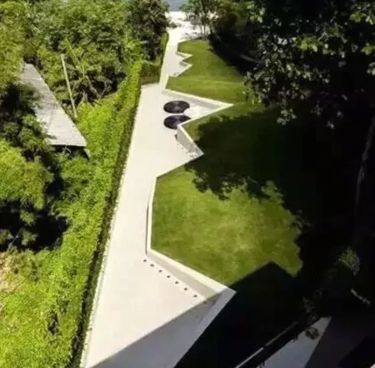 Canopy obstructionBoundaries and passages
Define the solution around actual operating conditions.
Canopy and buildings obstruct satellite signals; walls can introduce multipath. Mowers need controlled operation across open and degraded-signal areas.
Branches, toys, furniture, people and pets differ in appearance and size. Low obstacles can lie in blind spots; one sensing method does not cover every condition.
Irregular lawns, exclusion zones, connecting passages and dock placement determine routes. Positioning alone does not provide a complete mowing workflow.
Combine GNSS, IMU, VIO and visual SLAM with stereo depth and scene understanding. Integrate navigation, planning, cutting and chassis control in layers, with defined machine operating limits.
Combine pose, motion and observations into navigation outputs
Connect existing controls and safety strategies through agreed interfaces.
Configure missions, records and feedback with the application system.
Combine inertial and visual information as GNSS conditions change. Evaluate canopy, walls, repetitive texture and lighting, then configure slower operation or pauses according to localization status.
Stereo depth provides spatial observations and semantic perception supports object classification. Coordinate slowing, avoidance and exclusions with cutting safety, contact detection and braking.
Configure coverage using lawn boundaries, cutting width, exclusions and passages. Connect progress, resume points and docking to the machine task system to reduce overlap and missed areas.
Work zones, exclusions and passages
Cutting width, direction and turns
Track routes and respond to obstacles
Progress and localization status
Validate irregular boundaries, narrow passages and garden obstacles within the intended operating scope.
Coordinate activity periods, zone definitions and obstacle response with multi-area missions and records.
Test obstruction, repetitive structures, low clearance and terrain; confirm suitability against the base and sensors.
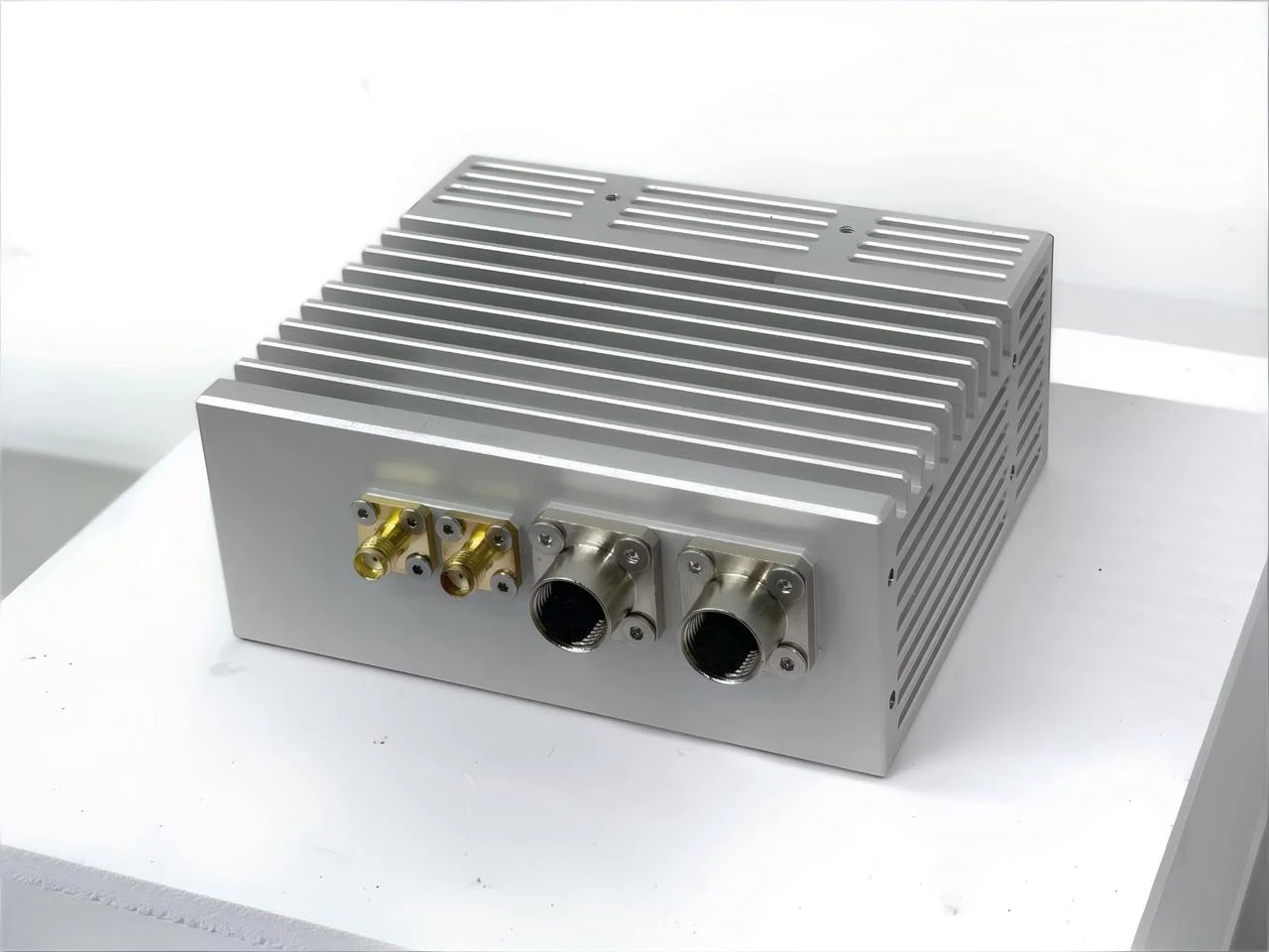 O1 / HopoEngine
O1-series form factor illustration
GNSS/IMU + monochrome stereo
Begin evaluation with O1. Integrate the mower base, controller, dock and sensor fields of view, selecting the configuration through field testing.
Agree operating conditions and acceptance targets before comparing field results.
Missed areas, overlap and boundary tracking
Canopy, walls, recovery and localization status
Low objects, moving targets and repeat docking
Capabilities depend on sensors, machine control, operating conditions and project scope. Confirm accuracy, perception and mission performance through field evaluation.
Define the environment, interfaces and delivered scope with HOPO.
Obstruction, lighting, texture and mounting affect the sensors differently. Fusion improves adaptability; validate localization and recovery on the target lawn.
Navigation and work-zone definition are separate functions. Virtual boundaries, mapping or other boundary methods depend on the mower design and site conditions.
Navigation and perception provide inputs. Docking, battery management, cutting control and safety interlocks require the respective machine systems. Define the delivered scope clearly.