01
Canopy and degraded positioning
Trees, terrain and nearby structures reduce satellite visibility. GNSS alone may not cover an entire working route.
Impact: deviations, overlap and missed strips
Connect fused positioning, perception and machine control, from open fields to orchards under canopy. Build precision operations on navigation that can be validated in the field.
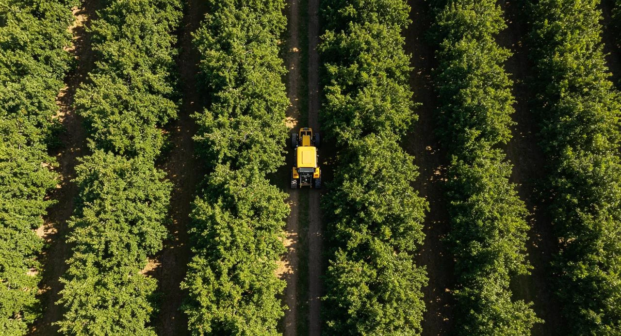 Canopy obstructionRow operations
Define the solution around actual operating conditions.
Trees, terrain and nearby structures reduce satellite visibility. GNSS alone may not cover an entire working route.
Uneven ground changes machine attitude, while mounted or towed implements have offsets. Receiver position is not the same as the working point.
Backlighting, dirty lenses and dust affect vision. Remote fields also require separate assessments of corrections and communications.
Use HopoEngine as the fusion foundation, configuring sensors, calibration and control interfaces for farm machines and robots. Define the operating scope, then validate tracking and exception handling.
Fuse position and attitude with depth and status outputs
Connect existing controls and safety strategies through agreed interfaces.
Configure missions, records and feedback with the application system.
Combine GNSS, IMU and vision to improve adaptability during temporary obstruction. Calibrate sensor extrinsics, mounting height and implement offsets to align navigation with the working point.
Connect planning and control using field boundaries, row spacing, implement width and turning limits. Evaluate headland turns, overlaps and missed areas across field operations.
Choose vision and radar for the environment to support traversable-space and obstacle perception. Treat correction links and business communications separately, configuring local tasks and reporting by project.
Boundaries, working width and exclusions
Spacing, turns and implement offsets
Track the route and perceive surroundings
Tracks, exceptions and coverage
Connect navigation to existing controls for seeding, tillage and crop care.
Validate canopy positioning, narrow-row access, turns and dynamic obstacles.
Connect tracks, status and task records as needed. Remote sensing and multispectral monitoring require dedicated payloads and systems.
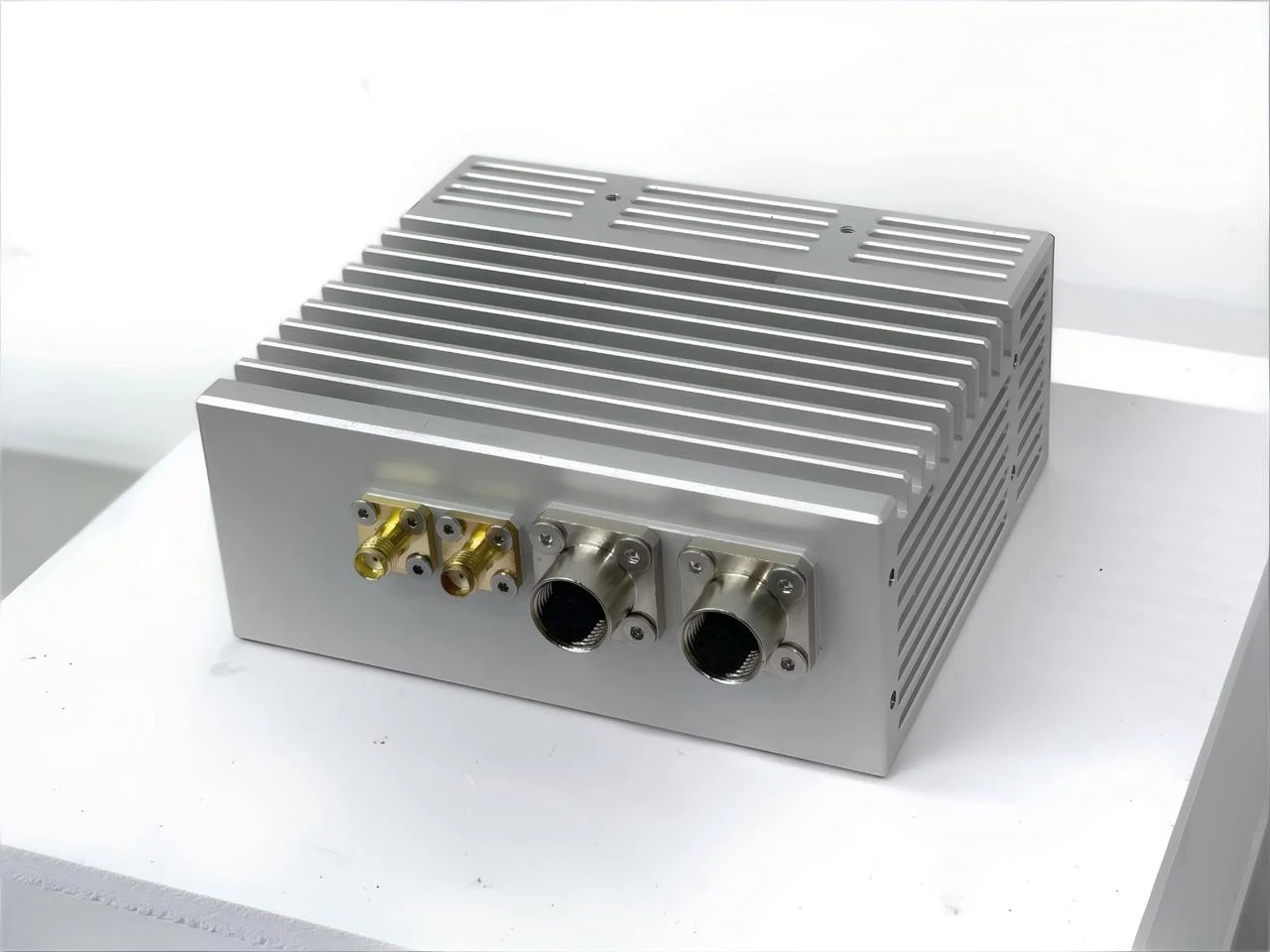 O1 MAX / HopoEngine
O1-series form factor illustration
GNSS/IMU + monochrome stereo + mmWave radar
Begin with O1 MAX and the machine control interface, evaluating vibration, mounting, sensor fields of view and implement offsets.
Agree operating conditions and acceptance targets before comparing field results.
Cross-track error, overlap and missed coverage
Obstruction duration, recovery and attitude stability
Slopes, dust, lighting and link variation
Capabilities depend on sensors, machine control, operating conditions and project scope. Confirm accuracy, perception and mission performance through field evaluation.
Define the environment, interfaces and delivered scope with HOPO.
Confirm correction sources, local navigation and remote communications separately. Local execution may be suitable for some tasks; validate corrections, remote intervention and status synchronization in the field.
Integration with existing steering or control systems can be evaluated. Feasibility depends on the machine, actuators, interfaces, mounting space and safety strategy. Start with prototype integration and field tests.
LEO augmentation is a HOPO research direction. Coverage, receiver compatibility, correction delivery and service availability must be confirmed for each project.