
01
Repetitive work and exposure
Distributed assets and frequent rounds create repetitive work. Heat, noise and restricted passages complicate access and fragment records.
Impact: recurring effort and site exposure
Navigate repeatedly to inspection points and combine visual, thermal or task-specific sensors with data capture, anomaly assessment and remote collaboration.
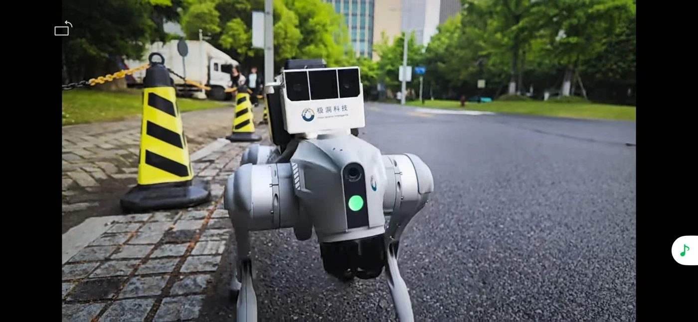 Platform motionEnvironment sensing
Define the solution around actual operating conditions.
Distributed assets and frequent rounds create repetitive work. Heat, noise and restricted passages complicate access and fragment records.
Narrow passages, transitions and uneven ground affect access. Legged-platform motion also changes sensor pointing and observations.
Inspection goes beyond photographs. Readings, thermal or acoustic anomalies need asset, time and location context, alerts and follow-up actions.
HopoEngine and navigation devices support pose and environmental perception. Payloads capture inspection data; the inspection platform handles analysis, records and collaboration. Clear responsibilities support integration.
Navigation and attitude outputs for access and observation
Connect existing controls and safety strategies through agreed interfaces.
Configure missions, records and feedback with the application system.
Configure asset points, rounds and access constraints. Fused positioning and perception support access, coordinated obstacle handling and exception stops.
Select visual, thermal or task-specific sensors. Align observations using timing, mounting calibration and attitude information to support comparable repeat measurements.
Integrate gauge reading, thermal or acoustic analysis by project and associate results with asset records. Define thresholds and human review for detection, response and re-inspection.
Frequency, route and payload
Route tracking and perception
Images, temperature, readings or sound
Human confirmation and response records
Evaluate navigation and capture against electromagnetic, mounting and network conditions. Confirm certification and protection needs by project.
Connect workshops and outdoor routes with repeat rounds, readings and exception records.
Validate stairs, ramps and uneven paths with the base, attitude changes and payload field of view.
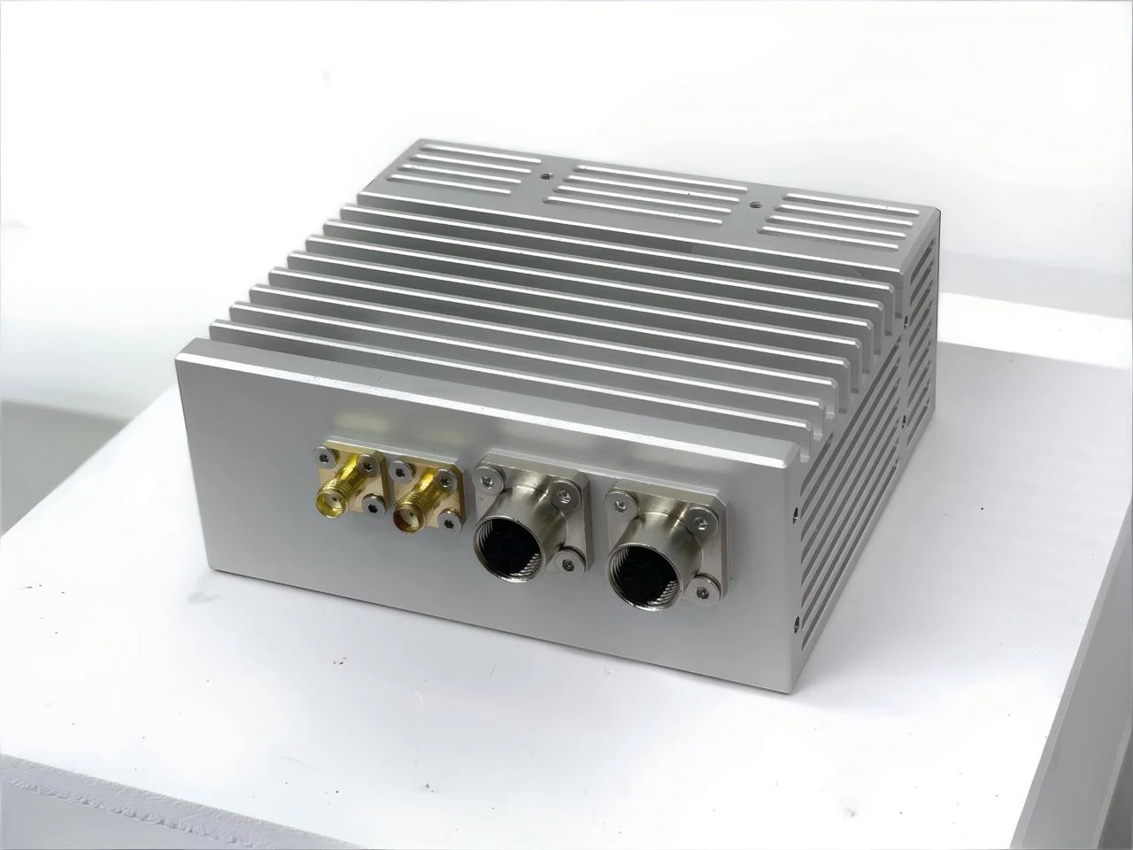 O1 MAX / HopoEngine
O1-series form factor illustration
GNSS/IMU + monochrome stereo + mmWave radar
Use O1 MAX as a starting point for multimodal navigation and perception. Integrate inspection payloads, the robot base and platform interfaces; diagnostic applications provide the task-specific analysis.
Agree operating conditions and acceptance targets before comparing field results.
Point access, route error and viewing angle
Completeness, time alignment and repeatability
Detection, false alerts and review process
Capabilities depend on sensors, machine control, operating conditions and project scope. Confirm accuracy, perception and mission performance through field evaluation.
Define the environment, interfaces and delivered scope with HOPO.
The device provides navigation and related perception. Thermal imaging requires a payload; OCR and diagnosis are handled by applications and platforms. Confirm the delivered scope for each project.
Verify the complete machine, payload, battery and communications against required certification, protection and operating conditions. Generic navigation capability does not establish hazardous-area certification.
Evaluate connections for inspection points, asset IDs, mission results and exceptions. Define formats, timing, access and network conditions before integration.